Deploy OPNSense Site-to-Site VPN
May 31, 2025
Table of Contents
- Our Setup
- Dynamic DNS with CloudFlare
- WireGuard Setup
- Firewall Rules on Your WAN Routers
- Firewall Rules on OPNSense
- Run Connection Tests
- Troubleshooting via SSH
- Troubleshooting Tips
- Tweak 1: Endpoint Under Multi-WAN Setup or DynDNS?
- Tweak 2: Prevent UDP Fragmentation
- Tweak 3: Monitor Your Tunnel with UptimeKuma
Our Setup
- Site 1 (U Vody):
- LAN: 192.168.8.0/24
- WAN: uvody.bachelor-tech.com (DNS record managed via DDNS to CloudFlare separately)
- WG tunnel: 10.10.10.1/24
- Site 2 (Tusarka):
- LAN: 192.168.6.0/24
- WAN: tusarka.bachelor-tech.com (DNS record managed via DDNS to CloudFlare separately)
- WG tunnel: 10.10.10.2/24
Dynamic DNS with CloudFlare
- Create an API key that allows zone editing for your domain.
- Create A records for each of your VPN site on your domain - do not hide the real addresses.
- Add them in OPNSense under Services → Dynamic DNS
Since both sites are likely behind residential or business ISP connections without a guaranteed static IP, dynamic DNS keeps each WAN hostname pointing at the correct address whenever it changes. This matters for the VPN because WireGuard does not re-resolve the hostname on every packet, it only does so once when the tunnel starts (more on that under Tweak 1 below), so a stale DNS record can leave a tunnel unable to reconnect after an IP change. Once you've added the Dynamic DNS entries in OPNSense, confirm the record is updating by comparing the IP shown in your CloudFlare dashboard to your WAN interface's current address.
WireGuard Setup
- On Site 1, go to VPN → WireGuard → Instances. Create a new one.
- Name: As you see fit, such as WG_S2S_to_Tusarka
- Public/private key - leave blank, they will be auto-populated on save.
- Port: default one is 51820, if you already have an instance (such as for a Client VPN with Road Warrior or believe in security by obscurity), use another one, such as 51821.
- Tunnel address: the IP of the WG endpoint, such as 10.10.10.1/24 .
- Depend on (CARP): in case you more than one OPNSense units on your LAN, it is important that only one of them initiates the tunnel. This is handled by CARP that would have been set up previously. Choose the CARP for your LAN interface to determine when a switch-over has taken place.
- There will be no peers to select yet (later, it will be the peer defined on this host for Site B).

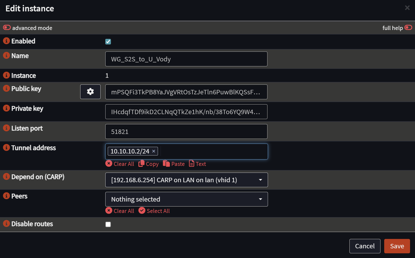
- On Site 2, do basically the same thing. Create a new instance under VPN → WireGuard → Instances.
- The listen port should match.
- The tunnel address needs to be on the same subnet but unique, such as 10.10.10.2/24
- Depend on CARP is optional in case you have your site 2 set up with high availability in terms of having two or more OPNSense units.
- We still do not have a peer to define.
- On Site 1, set up a peer. Still under VPN → WireGuard → Peers, add a new one.
- Name is as your second site - peer.
- Insert the public key of the instance from Site 2.
- Shared secret: leave empty
- Allowed IPs: add the remote tunnel (from site 2) specific /32 IP address + the remote LAN subnet.
- Endpoint address: Either the IP address of the Site 2’s WAN connection OR a hostname that you manage using dynamic DNS.
- Filling this field is actually optional if you prefer to keep Site 2 as the ‘client’ that will initiate the connection (like dialling a phone number), whereas Site 1 only responds as a ‘server’. However, if both sides have DynDNS-managed hostnames or static IPs, it is okay to fill it in for both.
- Endpoint port: the same as you used previously.
- Instances: Link it to the instance you defined earlier for Site 1.
- Keepalive interval: WG documentation states that 25 seconds should be used for UDP sessions behind a NAT to prevent it from going offline and re-starting.

- On Site 2, under VPN → WireGuard → Peers, add a new one.
- Public key should be taken from the public key of the Site 1 Instance (not peer!).
- Pre-shared key: leave blank
- Allowed IPs: The specific (/32) site 1 tunnel’s interface + the subnet of the Site 1 remote LAN.
- Endpoint address: This one is not as important for the second site that connects to the first one, but it is still worth filling in if you have a stable hostname or static IP for it.
- Endpoint port: as before
- Instances: Map it to the Site 2’s instance
- Keepalive interval: same as before 25s

- Assign the WG interface on Site 1. Go to Interfaces → Assignments and ensure that you have an assignment for the newly created interface (in my case, this was wg1). Give it a name that ideally starts with WG_S2S and then the name of your site. This will help to distinguish it from another WG instance you may implement in future (or have already) for a Road Warrior instance (VPN server to endpoint clients).
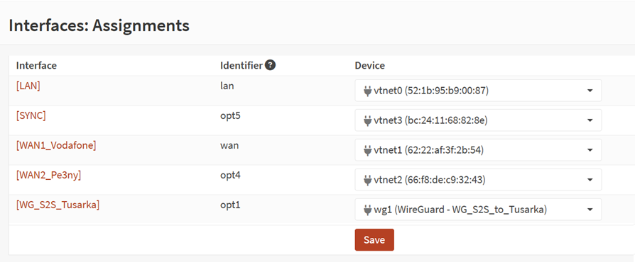
- In the same way, assign the WG interface on Site 2 (under Interfaces → Assignments).
Firewall Rules on Your WAN Routers
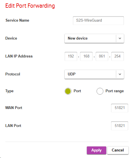
- Whether you have one or more WAN connections, they need to forward the traffic on the UDP protocol on the port that you defined (such as 51820 or 51821) to the OPNSense unit (if you have CARP set up for HA, then use the CARP LAN address).
- In this case, I configured the Site 2 WAN1 ISP router on the 192.168.61.0/24 subnet and the WAN1 interface on Site 2's OPNSense firewall has a CARP virtual IP of 192.168.61.254/24. If you do not use CARP, you could set it up as another IP (just not 192.168.61.1, since that is the gateway of the ISP router).
- Log into your ISP’s router (unless it is in bridge mode, in which case you do not need to take any action) and add a port forwarding rule. It will most likely look differently on your side. In the case of a standard consumer Vodafone router, it looks as follows:
- Theoretically, you only need to set it up on the ‘server’ node of your S2S VPN tunnel to which the ‘client’ dials in. In case either one can initiate the connection, it is best to allow it for both sites on all WAN routers.
- Make sure you cover all WANs so that in case of a WAN fail-over, the tunnel will not go down for more than a few seconds.
Firewall Rules on OPNSense
- Define aliases
- On Site 1, go to Firewall → Aliases and define a new alias:
- Name: WG_Public_IP_Peers (or if you will just have one site, then call it by the site’s name, just indicate that it will be a public address).
- Content: your public interface of your other site(s).
- On Site 1, go to Firewall → Aliases and define a new alias:

- **On Site 2**, create the same or similar alias with the other endpoint’s name (or direct static IP) in the content box.
- Create another alias for the remote LAN of each OPNSense site. **On Site 2**, create the following:
    - Name: Your remote LAN’s name
    - Type: Network(s)
    - Content: Your remote LAN’s subnet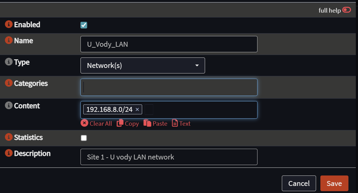
- Do the same **on your Site 1**’s OPNSense for Site 2’s remote LAN subnet. We will be using them in our firewall rules (on their own, they have no effect whatsoever).- A passthrough rule on each WAN interface on site 1 and site 2.
- The first thing is to pass the encrypted traffic from WAN so it can be decrypted and processed further.
- On Site 1, go to Interfaces Firewall → Rules → WAN (in case you have more WANs, do it for each one). Add a new rule:
- Quick: tick the box
- Interface: WAN
- Direction: in
- Protocol: UDP
- Source: any
- Destination: other - choose your port, such as 51821.
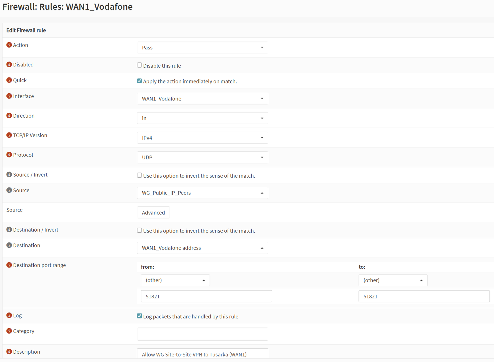
- Do the same **on** **Site 2** for each WAN interface. This is absolutely essential for the bridge to work.- Allow traffic on the WG interface for Site 1.
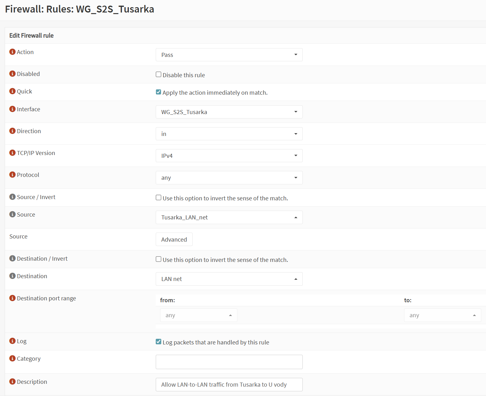
- On Site 1, go to Firewall → Rules → WG_S2S Interface. Create the following rule:
- Action: Pass
- Interface: WG_S2S for site1
- Direction: in
- Source: your alias for site 2’s LAN
- Destination: LAN net
- Port: any
- On Site 1, go to Firewall → Rules → WG_S2S Interface. Create the following rule:
-
Similarly, do the same on Site 2 to allow traffic on the WG interface (allow the remote LAN to reach the LAN on Site 2).
-
Allow LAN access from Site 1 to Site 2.
- While previously, we configured the tunnel’s interface (10.10.10.x/32) to accept traffic from the remote LAN and pass it to the local LAN, we have not yet allowed LAN to reach the remote LAN.
- On Site 1 on the LAN interface, add the following rule:
- Action: Pass
- Interface: LAN
- Direction: In
- Protocol: any
- Source: LAN net
- Destination: Site 2’s remote LAN (use your pre-defined alias)
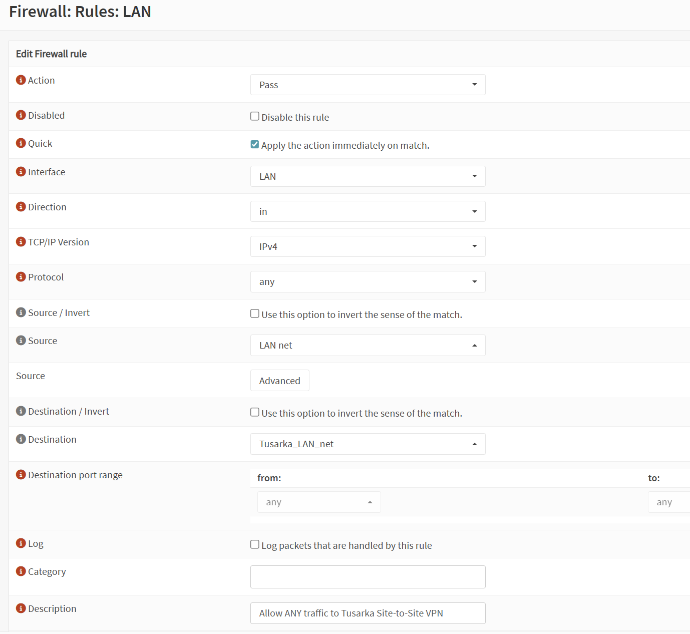
- Allow LAN access from Site 2 to Site 1. **On your Site 2**, apply the same step, just swap the alias’ name with the one you configured there for Site 1’s LAN.
- Note: At this point you will not be able to send ICMP packets (pings) from one tunnel address to another (such as from 10.10.10.1 to 10.10.10.2) even if the tunnel is up. This is because we have not (yet) enabled that on the WG S2S Interface. This is useful for monitoring - see a later step called ‘Tweak no.3’ to set it up.
Run Connection Tests
At this point, you can give your site-to-site tunnel a few tests. Try the following:
- On each OPNSense unit, check the WG Status page under WireGuard → Status to see that the instance and peer on each site are online, both sending and receiving data.

- Check also the WireGuard → Log File page.
- On Site 1’s OPNSense, run a ping test to ping the Site 2’s LAN interface from the Site 1’s LAN interface. From Interfaces → Diagnostics → Ping
- This way, we confirm that we can reach the remote LAN.
- Feel free to then change it to reach other devices on the remote network.
- Then switch to Site 2 to ping Site 1’s resources.

Troubleshooting via SSH
In case you can reach SSH on your OPNSense firewall(s), you can run some commands that will help you with getting a clear picture without the GUI:
- Check the status of your Wireguard interface. Look for the latest handshake. If you see one within the last couple of minutes, the tunnel itself is likely up. If not, there's a problem with keys, endpoints, or firewall rules on the WAN interface. Also, check transfer stats (rx/tx) to see if any data is moving. Sometimes it is sending but not receiving, which indicates an issue on the other site.
wg show- Ensure that the routes work as expected:
netstat -rn- Watch tcpdump for packets in traffic - you can get the name of the interface from the WebGUI of OPNSense or, if the unit is virtualized (such as on Proxmox), then rather from the SSH connection before you enter the shell. On Proxmox, instead of having a ‘wan’ interface, it may be called ‘vtnet1’, etc.
# Check for ICMP traffic on the LAN interface
tcpdump -i <lan_interface_name> -n icmp

# Check for encrypted WireGuard traffic on the WAN interface
tcpdump -i <wan_interface_name> -n udp port <wireguard_port>

# Check for decrypted ICMP traffic on the WireGuard interface
tcpdump -i <wireguard_interface_name> -n icmp
- You can also use the command below to show all active connections being tracked by the firewall - such as for testing icmp packets (pings):
pfctl -s state | grep icmp

# Ping the remote OPNsense router's tunnel IP from the local router's tunnel IP
ping -S <local_wireguard_ip> <remote_wireguard_ip>

# So from your site1, you can specify the source and try pinging the destination in the tunnel:
ping -S 10.10.10.1 10.10.10.2
Troubleshooting Tips
- If you add additional rules because you believe you are blocked, name them with a DEBUG prefix to be able to then tell what was added later and what was there before (for an easier clean-up later).
- In case your OPNSense is connected to a consumer router, make sure that you have set up a port forward for UDP/51820 (or whichever port you use) to the OPNSense firewall’s IP address (or preferably, the CARP LAN address if you have it set up).
- You do not need to port forward other ports for the purpose of the S2S VPN, because all traffic is encapsulated and sent via the secure tunnel - the ISP router has no idea what is in this encrypted packet.
- Cannot reach local devices on the other site? A good start of debugging is to enable ‘log packets’ on each rule temporarily and then use the Firewall → Logs → Live view. Run a ping test from machine1 on Site 1 to a machine2 on Site 2 and you can watch on each OPNSense’s live logs, looking for ‘protocol: icmp’. What needs to happen:
- The ICMP packet leaves the LAN on site1
- The S2S interface passes it from site 2 (via the tunnel)
- The S2S interface on site 2 receives it.
- The LAN interface on site 2 receives it and replies back.
- The S2S interface on site 2 forwards it.
- The S2S interface on site 1 receives it and forwards it to the LAN net on site 1.
- From the above, you can see at how many levels a block may occur and how time-consuming troubleshooting can be.
Tweak 1: Endpoint Under Multi-WAN Setup or DynDNS?
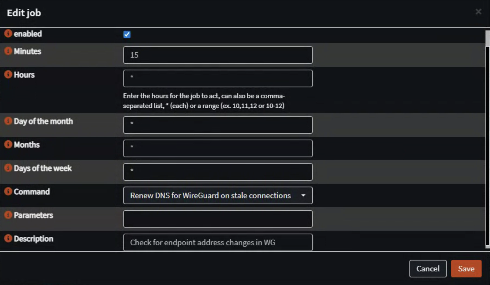
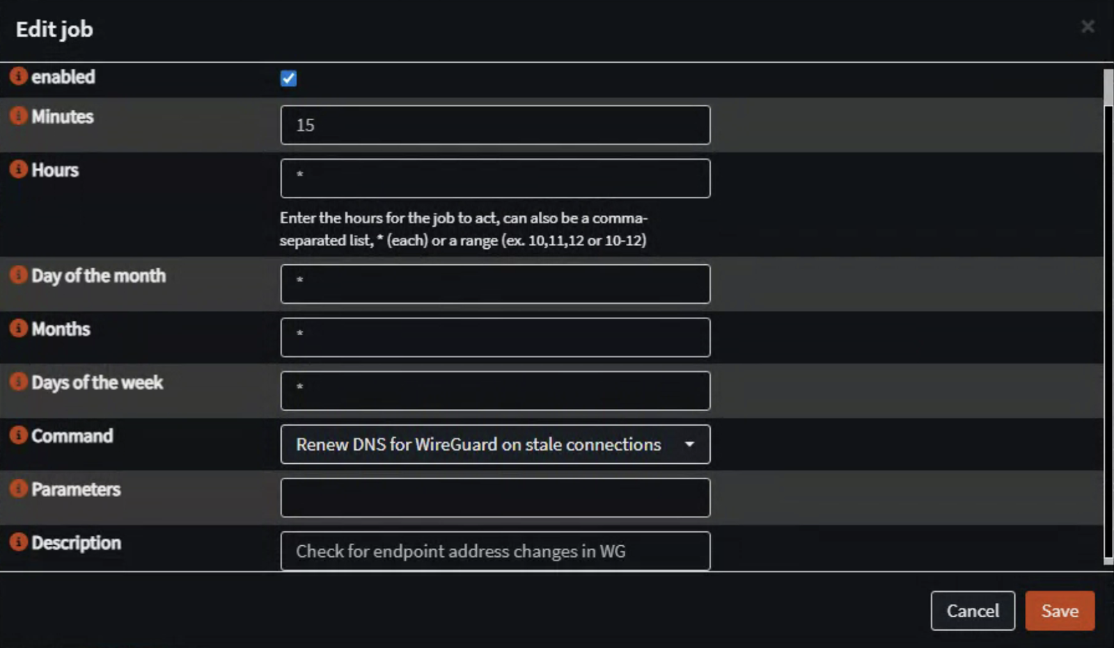
If you expect Site 1’s endpoint address to change regularly, be aware that according to OPNSense WG documentation, Wireguard only resolves the name once when the tunnel connection is started. This can be resolved by setting up a regular cron job.
- Go to System → Settings → Cron
- Add a new cron job:
- Set up the cron job to run every 5-15 minutes (enter 15 for Minutes and use * for the rest).
- As the command, choose ‘Renew DNS for Wireguard on stale connections’
- Apply the settings (make sure it is enabled).
Tweak 2: Prevent UDP Fragmentation
As per the OPNSense’s Wireguard guide, to prevent fragmentation of traffic going through the wireguard tunnel, the following measure can be applied. The documentation actually specifies the following:
By creating the normalization rules, you ensure that IPv4 TCP can pass through the Wireguard tunnel without being fragmented. Otherwise you could get working ICMP and UDP, but some encrypted TCP sessions will refuse to work. If you want to use IPv6 TCP, lower the MSS by 60 bytes instead of 40 bytes.
This will be done on each site:
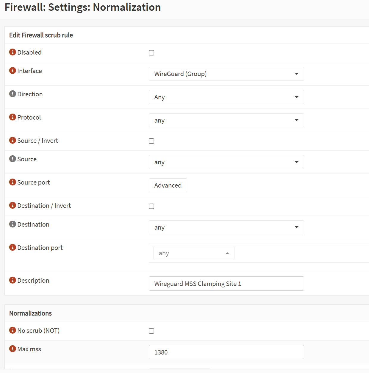
- On Site 1, go to Firewall → Settings → Normalization. Add a new rule.
- Interface: Wireguard (group)
- Direction, Protocol, Source, Destination: all as ‘any’
- Description: as suggested, ‘Wireguard MSS Clamping Site 1’.
- Max mss: 1380

- Do the same on Site 2.
Tweak 3: Monitor Your Tunnel with UptimeKuma
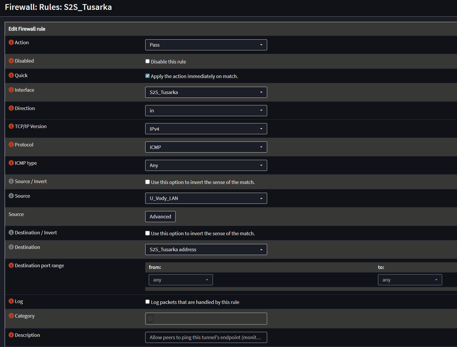
- To allow for monitoring of the tunnel’s uptime (such as by using UptimeKuma or Zabbix from Site 1), create the following rule on Site 2’s OPNSense:
- Action: Pass
- Interface: S2S
- Direction: in
- Protocol: ICMP
- ICMP type: any
- Source: Site 1’s LAN (use the existing alias)
- Destination: S2S address (which would be 10.10.10.2/32 in this case).
- Then add a ping monitor on your monitoring system of choice. The example below shows UptimeKuma (the screenshot below shows an example outage when I temporarily disabled WG on Site 2).

Enjoying this tutorial?
This site is a non-profit project. If it saved you some time, you can support it by getting Jan some coffee.
☕ Buy me a coffee
Comments